Crazy Rev Counter fixed - guide - GT-R Register - Official Nissan Skyline and GTR Owners Club forum

Go Back   GT-R Register - Official Nissan Skyline and GTR Owners Club forum > General > Nissan Skyline > Electronics
Register FAQ Members List Calendar Search Today's Posts Mark Forums Read

Notices


Reply
 
LinkBack Thread Tools Rate Thread Display Modes
Old 13th May 2011, 08:18 PM   #1 (permalink)
_dan_ is Looking for a new back box
GTR Register User
 
Join Date: Jan 2010
Location: Wokingham
Posts: 174
Crazy Rev Counter fixed - guide

Hi all, a few weeks back my rev counter started dancing about the place with a mind of it's own, read a few bits and bobs on here and had a go at it myself today, so thought Id write a bit of a guide for anyone else that fancies the job.

Took a couple of hours in all I guess.

I actually took the pictures when I was putting it back together again, but I'm sure you'll get the idea!

1) Unscrew gear knob, remove ashtray.

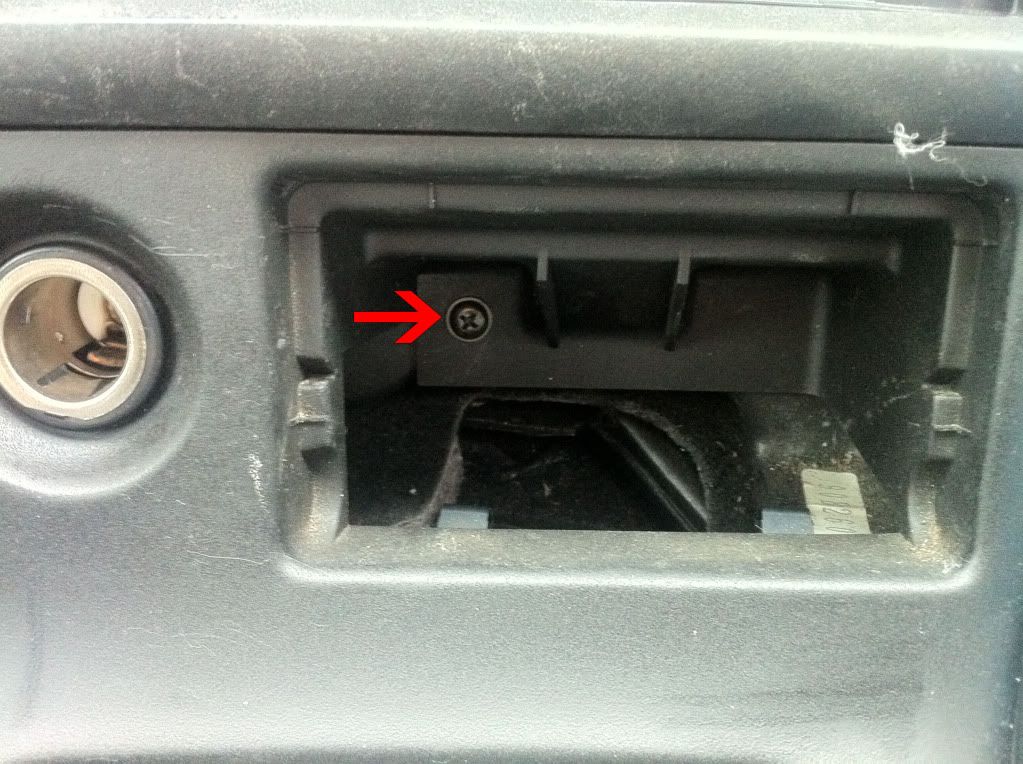
2) Remove screw behind ashtray. This is the only screw holding the gearstick surround in, the rest of it just unclips.


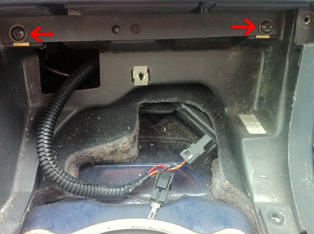
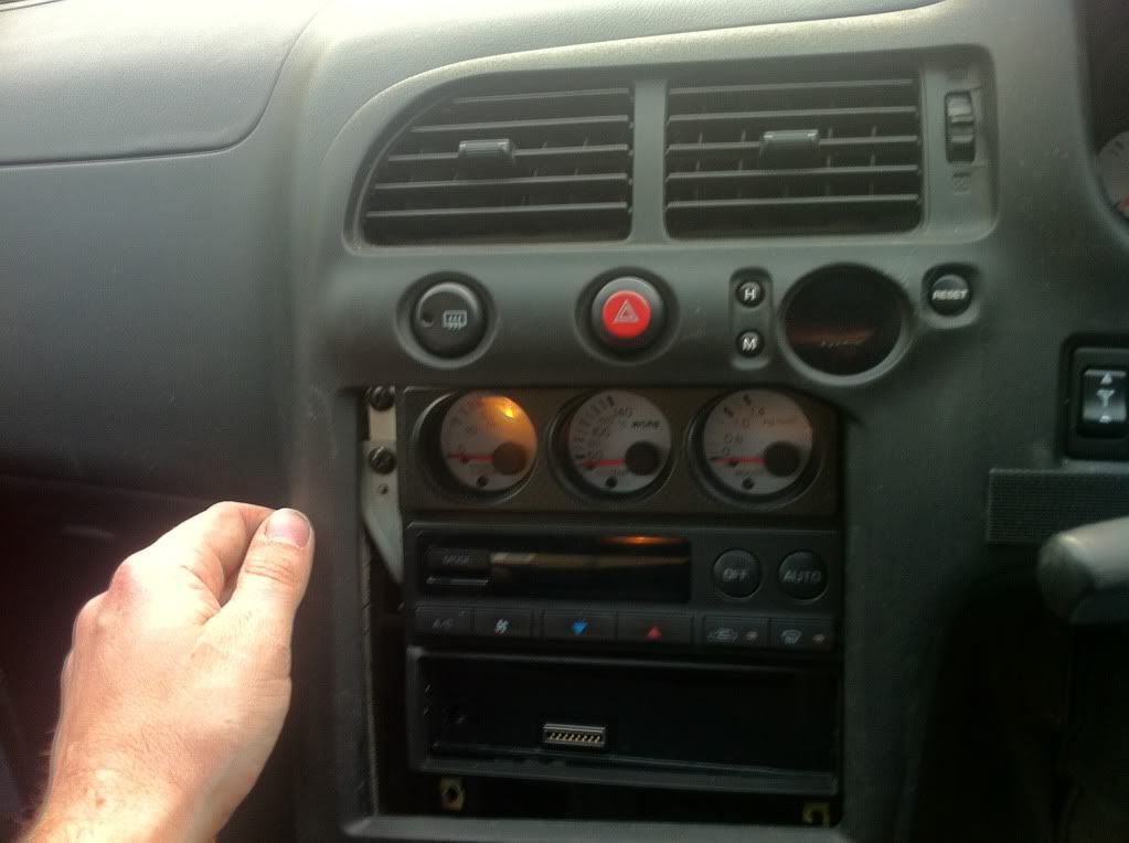
3) Once removed, remove the two screws behind that secure the dash facia


4) Next, for easier removal, the upper and lower steering column covers, 6 screws underneath, one sneaky one behind the adjustment bar! (No pics sorry)

5) Wasn't sure about this to begin with, but it turns out that the rest of the dash facia is just held on by clips, a few gentle tugs (!!) will dislodge the whole thing.


6) Once off, you'll need to remove all the multi connectors, there are a few, buttons, clock, temp sensor, mirror control and so on.

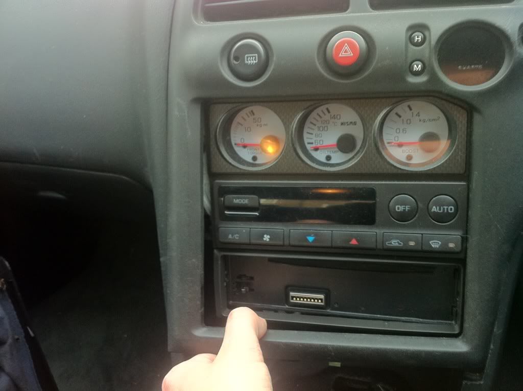
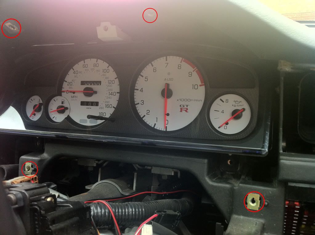
7) Next, remove the cluster surround (4 screws)....


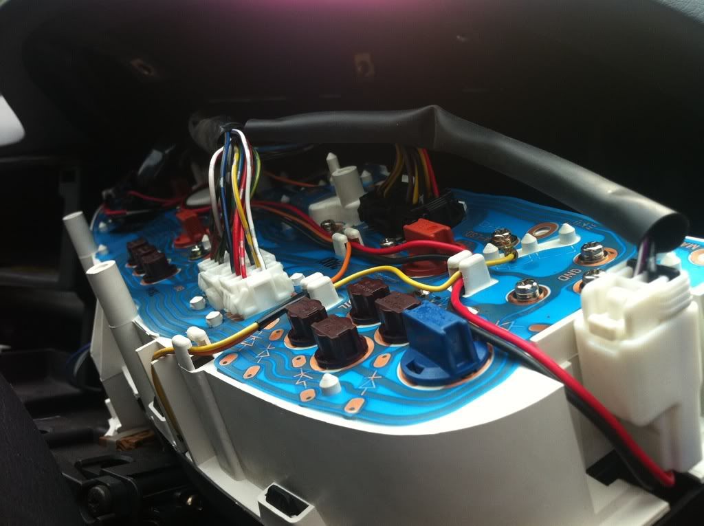
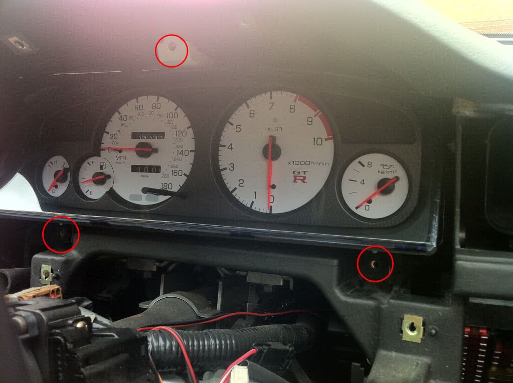
8) And then the three screws holding the actual cluster in....


I'll continue in the next post.....
__________________

Last edited by _dan_; 13th May 2011 at 08:20 PM..
_dan_ is offline   Reply With Quote
Old 13th May 2011, 08:56 PM   #2 (permalink)
_dan_ is Looking for a new back box
GTR Register User
 
Join Date: Jan 2010
Location: Wokingham
Posts: 174
Once the cluster is out, time to get to work, you'll need some half decent soldering skills, a solder sucker, some solder and of course a soldering iron with a relatively fine tip.

I read all of this on another very useful thread by andy42uk (The R33 rev conter problem fix)

1) First off, make a note of where the A-LSD wire connect (orange and yellow), and unscrew, not a great photo showing where they are! .....


2) Remove the clear plastic front cover, and the plastic surround, by unclipping them carefully, so that you end up with this....


3) Remove the three screws that hold the rev counter in...


4) Next, you'll need to detach the PCB on the back from the needle and motor, it makes everything alot easier to work with, and stops needle damage. I placed it face down with the needle between two books to work on it......

Here are the two screws and four solder points to allow the PCB to come free from the motor/needle....


.....and you end up with this......


5) Right then, now the hard part! I didn't take many shots here by the way! You'll need to remove, the IC, note that you should take ESD precautions to not damage the IC. It looks like Nissan (or the PCB manufacturer) put a bit too much solder resist around the pins (the green plasticy coating).

6) Remove the solder from all the pins, check that they are all free within their holes, and gently remove the IC, you may need to run the soldering iron over a couple of them to free them.

7) Next, using something like a scalpel, remove a bit of the solder resist green stuff to expose a bit more to solder onto, be very careful not to slice through any PCB tracks, or allow room for solder to flood from one pin to another. It's worth taking a bit of time dong this!

8) Now replace the IC, and resolder, go gently, and try not to hold the iron on each pin for too long else you may damage the chip, it's easy to put more solder on, harder to take it back off again.


9) You're done, put back together in reverse of removal.

There is a calibration screw on the PCB, but unless your counter is way off after this fix, I'd leave it alone.

Hope this is a bit of help to anyone who's willing to give it a bash, and I hope I haven't missed any bits out, I'm writing this after a couple of glasses of wine, and a few hours since I finished!

Dan
__________________

Last edited by _dan_; 13th May 2011 at 08:59 PM..
_dan_ is offline   Reply With Quote
Old 13th May 2011, 10:08 PM   #3 (permalink)
chinaone is stormtrooper
GTR Register User
 
chinaone's Avatar
 
Join Date: Apr 2010
Posts: 78
What is IC, PCD, ESD stands for?
What is it you replaced?
Did this work after you mod it, as I read on other threads, after a while it goes back like how it was before.
But well done for putting this up.
__________________
chinaone is offline   Reply With Quote
Old 13th May 2011, 10:13 PM   #4 (permalink)
_dan_ is Looking for a new back box
GTR Register User
 
Join Date: Jan 2010
Location: Wokingham
Posts: 174
Sorry, should've explained a little better, the link I posted explained it a bit.

PCB is printed circuit board
IC is Integrated Circuit (i.e. microchip)
ESD is Electrostatic Discharge - the static you have in your body can destroy a chip, so earth yourself first

Didn't replace anything at all, the solder joints between the circuit board and the chip commonly become weak due to there being not much for the solder to bond to on the board, over time heat an vibration can make the contacts bad, so I removed the chip, scraped off a bit of the plastic circuit board coating around each of the 20 or so pins of the microchip, and resoldered it back in again, good as new for now, but only did it today.

Maybe it'll be crap again in a week, I'll keep you posted!!
__________________

Last edited by _dan_; 13th May 2011 at 10:17 PM..
_dan_ is offline   Reply With Quote
Old 14th May 2011, 12:11 AM   #5 (permalink)
chinaone is stormtrooper
GTR Register User
 
chinaone's Avatar
 
Join Date: Apr 2010
Posts: 78
Thanks for the details, yea keep us updated.
__________________
chinaone is offline   Reply With Quote
Old 14th May 2011, 12:21 AM   #6 (permalink)
geoffree is unaware they can edit their status
GTR Register User
 
Join Date: May 2010
Posts: 138
With soldering skills like this, you'll have R32 owners lining up to fix the faulty clock.
Apparently a simple job once you UNSOLDER the vacuum tube without cracking it.
__________________
geoffree is offline   Reply With Quote
Old 16th May 2011, 10:43 AM   #7 (permalink)
_dan_ is Looking for a new back box
GTR Register User
 
Join Date: Jan 2010
Location: Wokingham
Posts: 174
Still, working!!
__________________
_dan_ is offline   Reply With Quote
Old 17th May 2011, 09:32 AM   #8 (permalink)
Mwohaaahaahaa is unaware they can edit their status
GTR Register User
 
Join Date: Feb 2010
Posts: 146
Thanks for putting this up Dan. It's nice that you have put how to take the dash off etc.. and where the screws are. I didn't fancy taking it all off as i didn't know where all the screws and that are, and i would probably end up breaking it some how. But i will probably give it a go now.
__________________
Mwohaaahaahaa is offline   Reply With Quote
Old 28th December 2012, 08:59 PM   #9 (permalink)
RadoGTST is ...
Executive GTR Owners Club Member
 
RadoGTST's Avatar
 
Join Date: Jul 2010
Location: London
Cars owned: R33 GTR
Posts: 439
Does anyone know if nismo clocks suffer from this problem too? (is circuit board printed the same way?)
Rev counter either works ok or needle jumps all over dial, I'm guessing it could be the same problem?

for andy42uk and dan
__________________
RadoGTST is offline   Reply With Quote
Old 1st January 2013, 03:04 PM   #10 (permalink)
Top Cat is unaware they can edit their status
New Users
 
Join Date: Mar 2008
Location: Hull
Cars owned: R33 GTR, 2ltr Robin Hood Track Car
Posts: 43
Do you still have the car Dan, and is the fix still working as I need to taclke this problem soon.
__________________
Top Cat is offline   Reply With Quote
Old 12th March 2013, 05:13 PM   #11 (permalink)
RadoGTST is ...
Executive GTR Owners Club Member
 
RadoGTST's Avatar
 
Join Date: Jul 2010
Location: London
Cars owned: R33 GTR
Posts: 439
Quote:
Originally Posted by RadoGTST View Post
Does anyone know if nismo clocks suffer from this problem too? (is circuit board printed the same way?)
Rev counter either works ok or needle jumps all over dial, I'm guessing it could be the same problem?

for andy42uk and dan
I will reply to my own question as I just did it and can confirm it's exactly the same on nismo clocks.
All solder points redone on microchip and... voila!
All good and working again
__________________
RadoGTST is offline   Reply With Quote
Old 8th April 2013, 07:06 PM   #12 (permalink)
Starbuck is in the process of registering his GTR
GTR Register User
 
Join Date: Mar 2010
Location: Luxembourg
Cars owned: 04 VW R32, 96 R33 GTR V Spec
Posts: 56
Looks like I will have to do the same to my Nismo revmeter. When I start the car the revmeter needle jumps all over the place and finally stays put at 11k rpm.
__________________
Starbuck is offline   Reply With Quote
Old 8th April 2013, 08:05 PM   #13 (permalink)
RadoGTST is ...
Executive GTR Owners Club Member
 
RadoGTST's Avatar
 
Join Date: Jul 2010
Location: London
Cars owned: R33 GTR
Posts: 439
All you got to do is step 1, 2 and 3 of this guide. Forget step 4 if you don't want/don't know how to de-solder it and take the whole revmeter to electronic repair shop or something similar.

The guy I found locally did it in under 5 mins and charged £5.
__________________
RadoGTST is offline   Reply With Quote
Reply

Bookmarks

Thread Tools
Display Modes Rate This Thread
Rate This Thread:

Posting Rules
You may not post new threads
You may not post replies
You may not post attachments
You may not edit your posts

BB code is On
Smilies are On
[IMG] code is On
HTML code is Off
Trackbacks are On
Pingbacks are On
Refbacks are On

Forum Jump


All times are GMT. The time now is 01:35 PM.


Powered by vBulletin® Version 3.8.4
Copyright ©2000 - 2013, Jelsoft Enterprises Ltd.
SEO by vBSEO 3.2.0
© 2001-2013 Cem Kocu

demoMedia